Virtualized Automotive Software Development: Co-Simulation with tracetronic ecu.test and Vector SIL Kit (2/3)
Author: Meik Schmidt
In our previous blog post, we explored how Virtual Platforms (VPs) can support early-stage hardware and software development. We showed that VPs can serve as drop-in replacements for physical hardware – especially when prototypes are not yet available. This approach enables earlier verification, helps detect software bugs sooner, and ultimately helps to reduce development costs and time to market.
To realize these benefits in practice, VPs must be compatible with widely used testing, debugging, and analysis tools. This is where standardized interfaces play an increasingly important role. By following common standards, different tools and simulators can be interconnected – enabling complex co-simulation environments that combine multiple subsystems. One such interface is Vector’s open-source SIL Kit solution, which is supported by MachineWare’s VPs. In this post, we will demonstrate how a VP can utilize this interface to use ecu.test, an automotive testing software from tracetronic GmbH, to validate embedded software in a simulation setup. First, we will introduce the SIL Kit framework, then we will discuss the demonstration scenario, and finally, we will examine further use cases for the software development workflow.
Co-Simulation and Vector SIL Kit
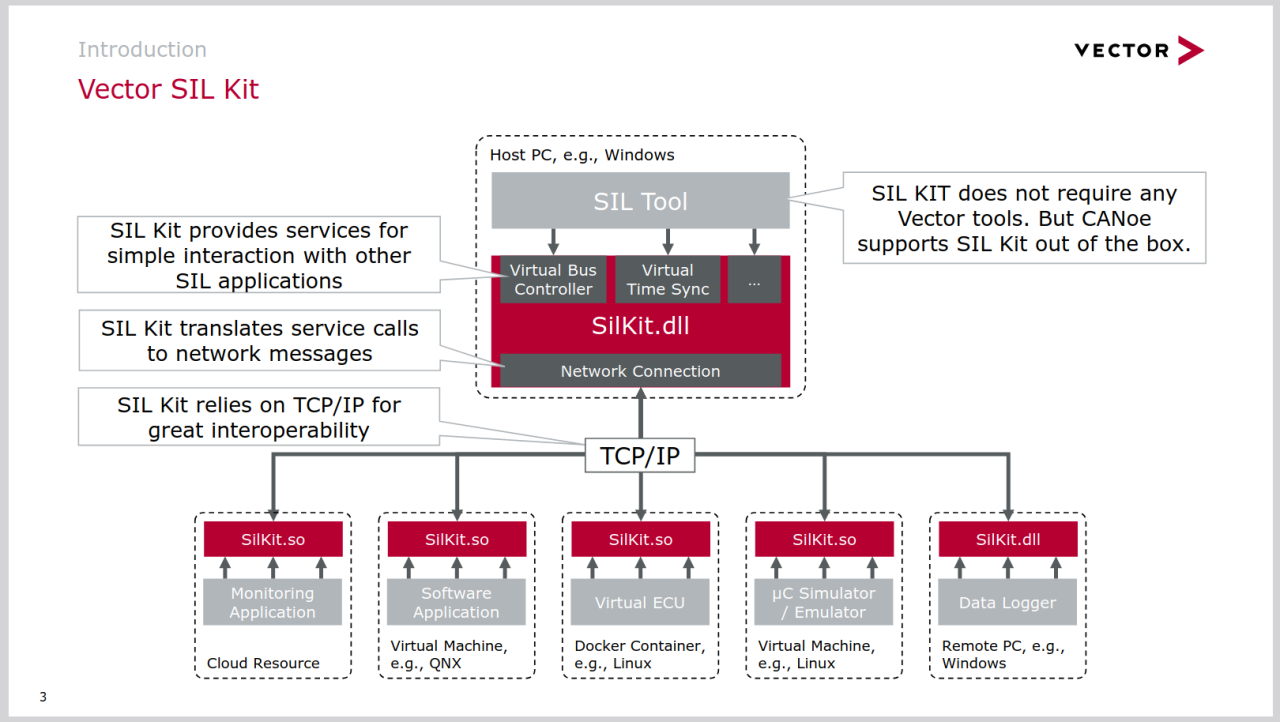
SIL Kit is a framework developed and maintained by Vector Informatik GmbH. It is an open-source library for connecting Software-in-the-Loop (SIL) environments. It provides data exchange mechanisms for widespread interconnect technologies like Ethernet, CAN, FlexRay, and LIN. Furthermore, it supports additional co-simulation concepts like virtual time synchronization. Several publicly available adapters exist for common simulation tools and interfaces, including QEMU, TAP devices, Linux SocketCAN, generic Linux I/O devices, and Functional MockUp Units (FMUs). Thanks to the SIL Kit ecosystem, users gain compatibility with many other tools and simulators.
MachineWare's VPs can be configured to utilize the SIL Kit interface for specific virtual devices. For example, if the VP contains a virtual CAN controller model, it can expose that interface via SIL Kit. In such a setup, all CAN messages generated by the VP are sent to other simulators through SIL Kit – and incoming messages are received in return. SIL Kit communication is handled over TCP/IP, allowing each simulator to run on a different machine or operating system. Figure 1 illustrates this setup: each simulator can run on a different host – be it a Windows PC, a Linux system, or a virtual machine – while still participating in the same synchronized co-simulation.

Importantly, SIL Kit is not limited to connecting simulators. Monitoring, debugging, logging, and testing tools can also access the data streams via SIL Kit. Many commercial tools already support this standard, which means that teams can continue to use familiar toolchains while integrating MachineWare's VPs into their development process.
This interoperability is especially valuable when it comes to meeting industry standards and safety requirements. Since VPs behave like real hardware, they can be used early in development to verify compliance with Automotive Safety Integrity Levels (ASILs) and other norms. For instance, achieving specific code coverage thresholds is often mandatory, and such metrics can be collected through standard test tools integrated with the VP. This can be accomplished using MachineWare's VPs in combination with industrial testing tools that provide coverage reporting. Similar requirements – such as fault injection, timing analysis, or traceability – can also be addressed using the same approach. VPs thus enable early verification in the design phase and contribute to a more efficient and standards-compliant software development process.
These use cases are best illustrated through demo scenarios. In the following demo, we will utilize the SIL Kit framework with one of MachineWare’s VPs in an exemplary application to connect ecu.test – an automotive testing software - and use its capabilities to verify the behavior of a user-space program running inside the VP. Although this scenario is artificial, it is closely related to real-world applications and demonstrates clearly how VPs can be integrated into existing design flows.
Initial Setup: A Co-Simulation with Virtual ECUs
Our demo scenario is built around ecu.test, a tool widely used in the automotive industry to test Electronic Control Units (ECUs). It supports various interfaces to interact with physical or virtual devices, send test data, and evaluate their behavior. These capabilities are crucial for verifying compliance with safety standards such as ISO26262 [2] for modern vehicles.
In addition to physical interfaces, ecu.test supports Vector’s SIL Kit interface, allowing seamless integration with Virtual Platforms (VPs). For example, when a VP is connected to a CAN bus via SIL Kit, ecu.test can monitor and validate messages sent on that bus – just as it would with real hardware.
The demo setup includes three simulated ECUs, that are typically found in a car:
-
ESP simulator: simulates wheel speed data from an Electronic Stability Program (ESP)
-
Rain sensor simulator: generates changing rain intensity values
-
Wiper simulator: adjusts wiper speed based on rain intensity
All ECUs communicate via a shared CAN bus. A test case in ecu.test verifies whether the Wiper ECU responds correctly to changing rain inputs by monitoring the bus and comparing it to the expected behavior. This setup is shown in Figure 2 on the left.

Integrating a Virtual Platform in the Scenario
Each of the vECUs is initially implemented in Python and simulates the ECU’s behavior at a high abstraction level. To demonstrate the integration of VPs and create a more realistic simulation setup, we replace the Wiper vECU with AVP64, an open-source ARMv8-based VP developed by MachineWare [3]. This VP boots an embedded Linux kernel created with the Buildroot project ([4], [5]) and runs a user-space application that implements the same behavior as the Python Wiper vECU. The new setup is shown in Figure 2 on the right.
Distributed Simulation: VPs and ecu.test on Separate Machines
To demonstrate the flexibility of this approach, we run the AVP64 and ecu.test on separate machines within the same network – one running Linux, the other Windows. Both applications connect to a central SIL Kit registry, which orchestrates the simulation and facilitates communication between the participants. It does not matter which of the two machines hosts the registry, as long as it is reachable by all components. The setup is illustrated in Figure 3.

Creating a distributed SIL Kit simulation with multiple participants is straightforward. After launching the SIL Kit registry on one machine, both AVP64 and ecu.test are configured to connect to it. In the configuration, the simulation network identifier and the CAN bus identifier must be specified. Once configured, both applications automatically connect to the registry and can communicate seamlessly.
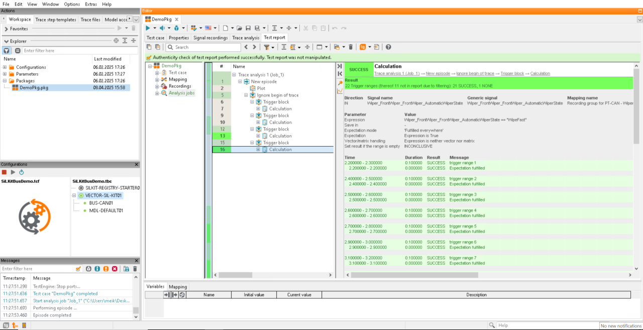
Since the VP replaces the original Python Wiper vECU, we deactivate it in ecu.test before starting the test. After AVP64 has booted and the user-space application is launched, the test case in ecu.test can be executed as usual – generating test reports, logs, and performance metrics. Screenshot 1 shows a sample report generated by ecu.test, which behaves exactly as it would with physical test hardware. Test case creation, execution, and reporting workflows remain unchanged. Moreover, these same test cases can be reused without modification once physical hardware becomes available – by simply switching the interface configuration to monitor a physical CAN bus instead of a virtual one. This is only possible because VPs simulate the physical hardware in sufficient detail to make them interchangeable. The same concept applies to other development tools. For example, coverage tools such as gcov can be used alongside ecu.test to generate coverage reports based on executed test cases.

Generating Coverage Reports for Test Cases
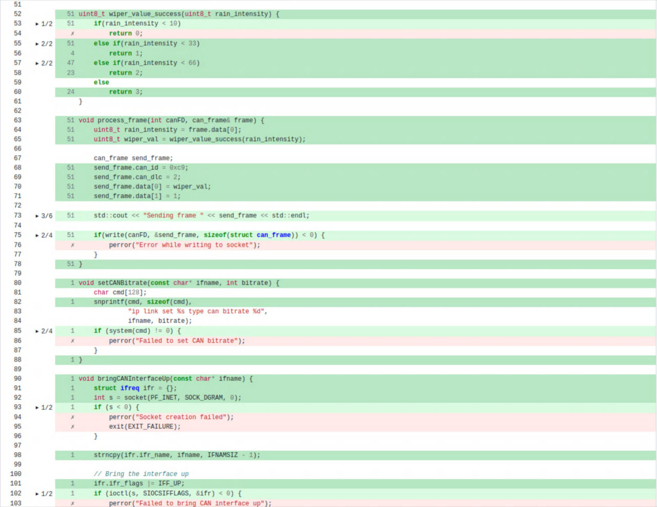
To generate coverage reports for the executed test case, one follows the same steps as if the application were running on the host platform. The process is straightforward:
-
Compile the application with coverage flags and link it against a mandatory library (generates .gcno files).
-
Run the compiled application on the VP (produces .gcda files during execution).
-
Use a tool like gcovr to analyze both files and generate coverage reports in different formats.
The report for our demo test case is shown in Screenshot 2. This mirrors the standard coverage process used with physical hardware and the generated reports can be used to accelerate compliance with industry norms and standards – long before physical ECUs are available.

Summary
This blog post has shown how MachineWare’s Virtual Platforms can be integrated into established testing workflows using Vector’s SIL Kit and tracetronic’s ecu.test. By replacing one of the simulated ECUs with a VP, we validated that existing test cases could run without modification – proving that VPs are viable hardware substitutes even in certified toolchains.
However, testing is only one part of the story. One of the key strengths of VPs lies in their ability to support everyday development workflows – especially debugging. With MachineWare’s VPs, developers can inspect low-level code such as operating system kernels or drivers, or trace the behavior of user-space applications running on the VP. This allows for early and convenient troubleshooting, even before physical hardware becomes available.
In the next blog post we will extend the demo scenario explained here and debug the application of the test case, while it is executing. We’ll use both open-source and commercial debuggers, such as GDB and Lauterbach’s TRACE32.
